Decision Tree Elements

    SpiceLogic Decision Tree Pro lets you build decision tree models with the following elements.

    Decision Node

    A decision node represents a choice that needs to be made. A decision node can contain several action nodes, and each action node represents one action the decision-maker can take.

    A decision node is shown with a square symbol.

    Standalone Decision node drawn as a square, the symbol used in Decision Tree Analyzer to represent a choice the decision-maker controls.
    Standalone Decision node drawn as a square, the symbol used in Decision Tree Analyzer to represent a choice the decision-maker controls.

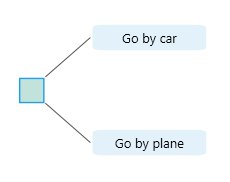
    With action nodes added, a decision node looks like this.

    Decision node with several Action node children attached, showing how acts branch out below a decision.
    Decision node with several Action node children attached, showing how acts branch out below a decision.

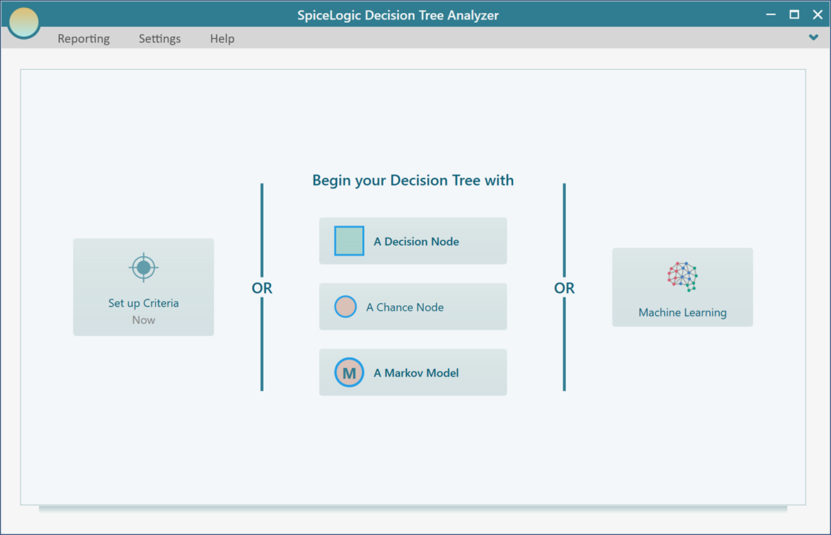
    To create a decision tree with a decision node as the root, click the Decision button on the start screen.

    Decision Tree Analyzer start screen offering A Decision Node, A Chance Node, or A Markov Model as the root, with Set up Criteria and Machine Learning shortcuts.
    Decision Tree Analyzer start screen offering A Decision Node, A Chance Node, or A Markov Model as the root, with Set up Criteria and Machine Learning shortcuts.

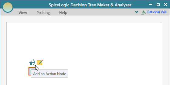
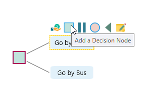
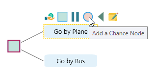
    A decision node can also be added under an action or event node. The software shows a fly-over menu when a node is selected. This menu only shows valid child node types for the selected node.

    For example, a decision node can contain action nodes. An action node can contain one decision node or one chance node. The screenshot below shows the fly-over menu for a decision node.

    Flyover menu on a selected Decision node listing only the valid child types it can contain (Action nodes).
    Flyover menu on a selected Decision node listing only the valid child types it can contain (Action nodes).

    After actions are added to a decision node, you can add another decision node under an action node.

    Flyover menu on an Action node with the button to add a Decision node as a child, building the next layer of the tree.
    Flyover menu on an Action node with the button to add a Decision node as a child, building the next layer of the tree.

    The tooltip on each fly-over menu button explains what the button does.

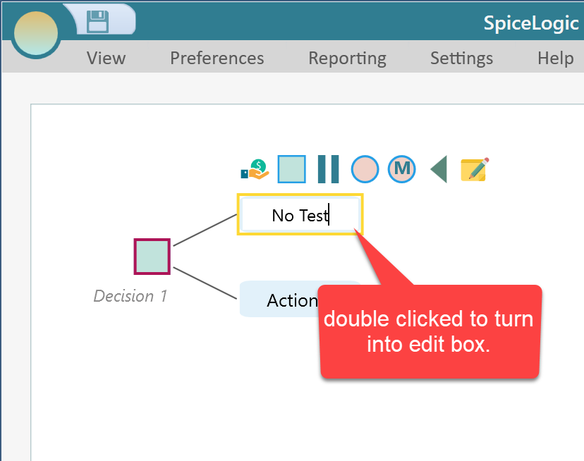
    After you add a node, double-click it to edit the text. Press Enter to save the change, or Esc to cancel it.

    Node turned into an inline editable text box after a double-click, ready for the user to commit with Enter or cancel with Escape.
    Node turned into an inline editable text box after a double-click, ready for the user to commit with Enter or cancel with Escape.

    Chance Node

    A chance node represents uncertainty. It is a random variable that can have several states, also called events. A chance node is shown with a circle symbol.

    Standalone Chance node drawn as a circle, the symbol used in Decision Tree Analyzer to represent an uncertain random variable.
    Standalone Chance node drawn as a circle, the symbol used in Decision Tree Analyzer to represent an uncertain random variable.

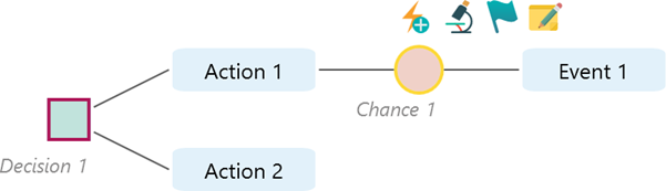
    With events added, a chance node may look like this.

    Chance node with several Event node children attached, showing the possible states of the uncertain variable.
    Chance node with several Event node children attached, showing the possible states of the uncertain variable.

    When a chance node is selected, its fly-over menu shows commands for adding events.

    Flyover menu on a Chance node with the Add an Event Node tooltip shown (the only valid child type for a Chance node).
    Flyover menu on a Chance node with the Add an Event Node tooltip shown (the only valid child type for a Chance node).

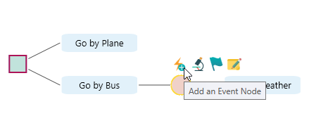
    You can add a chance node under an action node or an event node from the fly-over menu.

    Flyover menu on an Action node showing the circle button used to add a Chance node child.
    Flyover menu on an Action node showing the circle button used to add a Chance node child.

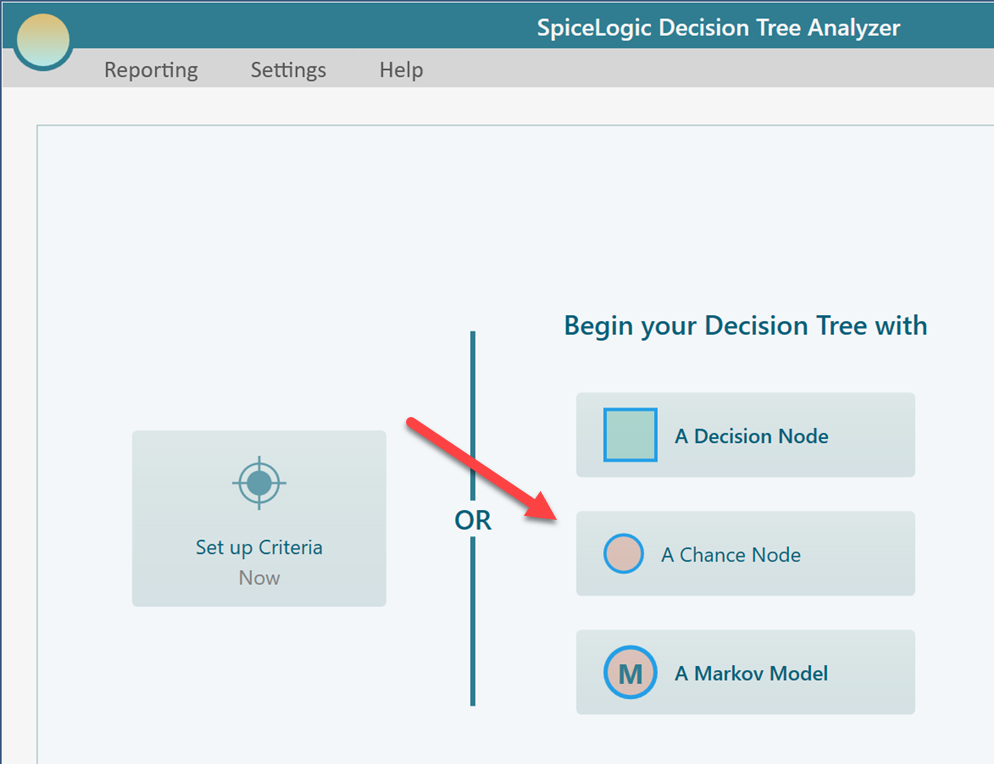
    You can also use a chance node as the root node. That is not the traditional structure of a decision tree, but Decision Tree Pro supports it so you can model cause-and-effect style trees.

    Cause-and-effect analysis tree built with a Chance node as the root, a SpiceLogic extension of the classic decision tree.
    Cause-and-effect analysis tree built with a Chance node as the root, a SpiceLogic extension of the classic decision tree.

    To use a chance node as the root, click the "Chance node" button on the start page.

    Decision Tree Analyzer start screen with the Chance Node button highlighted as the way to begin a tree with a Chance root node.
    Decision Tree Analyzer start screen with the Chance Node button highlighted as the way to begin a tree with a Chance root node.

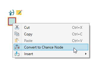
    You can convert a decision node to a chance node, or a chance node to a decision node. For example, if the root is a decision node, right-click it and choose "Convert to Chance node" from the context menu.

    Right-click context menu on a Decision root node with the Convert to Chance Node option for switching its type in place.
    Right-click context menu on a Decision root node with the Convert to Chance Node option for switching its type in place.

    Setting Probabilities

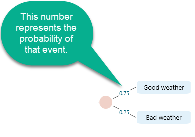
    A chance node contains event nodes, and each event has a probability. When a chance node has only one event, the software does not need to show a probability value. Because the events are mutually exclusive and collectively exhaustive, one event must have probability 1.

    Chance node with a single event child, where no probability is shown because a single event has probability 1 by definition.
    Chance node with a single event child, where no probability is shown because a single event has probability 1 by definition.

    After you add another event to the chance node, a question mark appears on the edge.

    Chance node with two events where each edge shows a question mark, indicating their probabilities are not yet set.
    Chance node with two events where each edge shows a question mark, indicating their probabilities are not yet set.

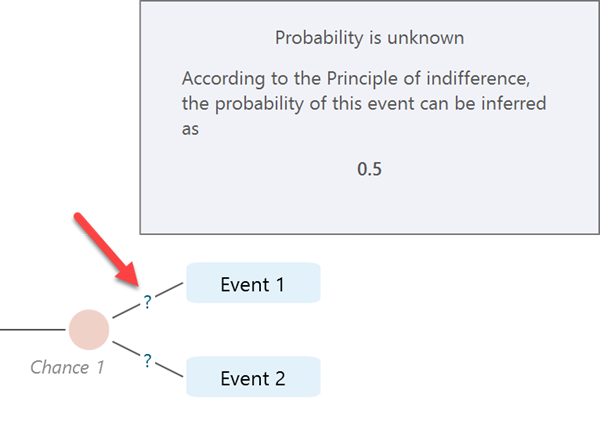
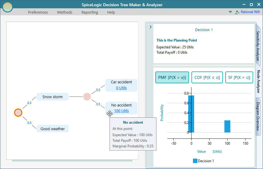
    When you do not specify probabilities, the software follows the principle of indifference. If there is no reason to believe one event is more probable than another, all events are treated as equally likely. With two events, each event has probability 0.5. You can see that value in the tooltip.

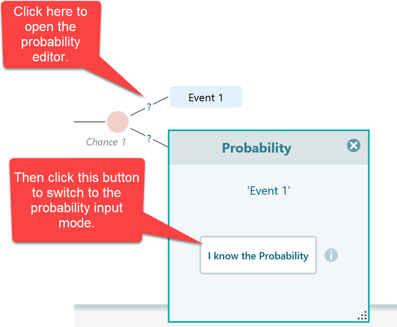
    To enter your own probability, click the question mark to open the probability editor.

    Probability dialog opened from the question-marked Event 1 edge with the I know the Probability button used to switch to explicit input mode.
    Probability dialog opened from the question-marked Event 1 edge with the I know the Probability button used to switch to explicit input mode.
    After setting one event probability, the sibling event probability is automatically adjusted so the values sum to 1.
    After setting one event probability, the sibling event probability is automatically adjusted so the values sum to 1.

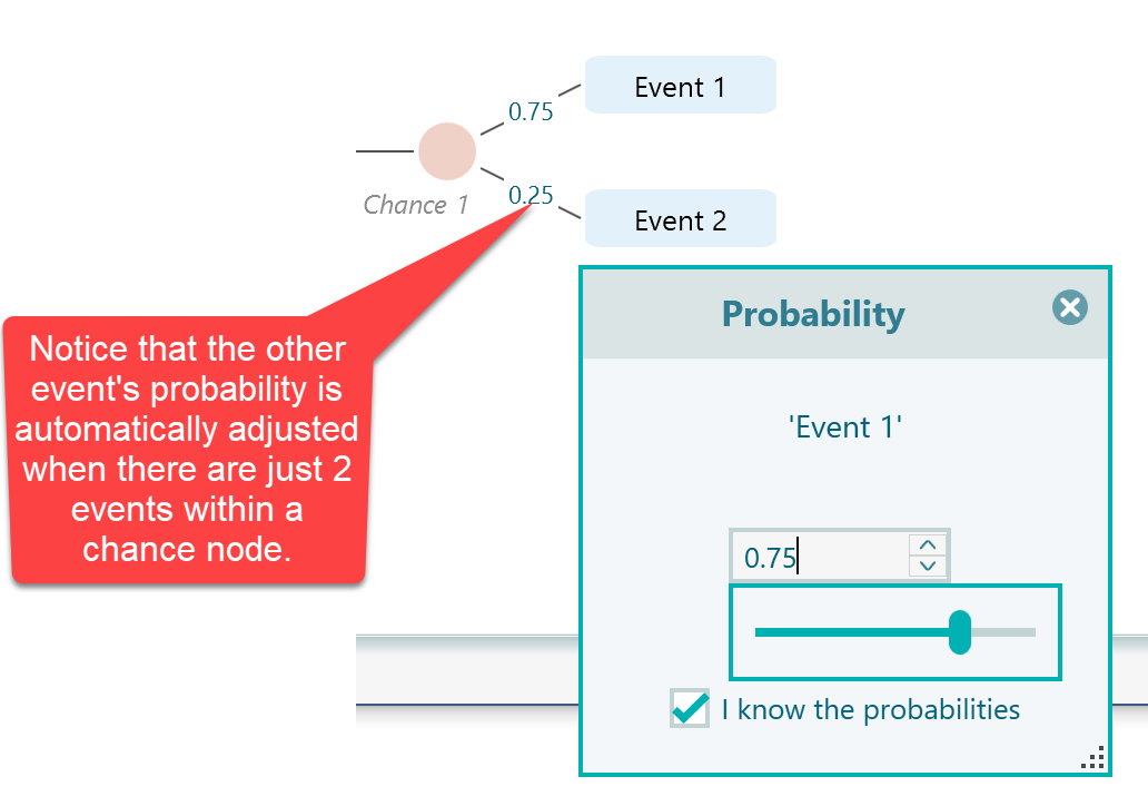
    When you change the probability of one event, the other event probability is adjusted automatically.

    If a chance node has three or more events, the software scales the probabilities so their sum is 1. The node shows the input probability, and the tooltip shows the scaled probability. If your input probabilities do not add up to 1, the software highlights the probabilities in red as a warning, but it still uses the scaled values for calculation.

    Three-event chance node where typed probabilities are shown on the edges and a tooltip reveals the auto-scaled normalised values.
    Three-event chance node where typed probabilities are shown on the edges and a tooltip reveals the auto-scaled normalised values.

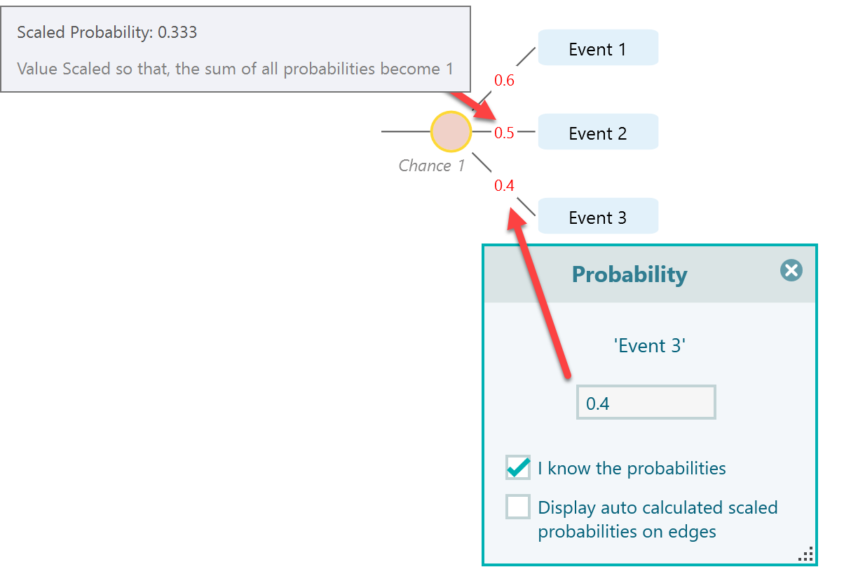
    To show the corrected scaled probabilities directly on the edges, check "Display auto calculated scaled probabilities on edges".

    Checkbox Display auto calculated scaled probabilities on edges turned on so the corrected normalised values appear directly on the edges.
    Checkbox Display auto calculated scaled probabilities on edges turned on so the corrected normalised values appear directly on the edges.

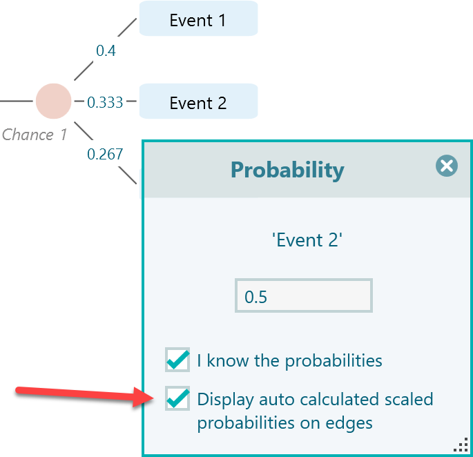
    This checkbox appears only when the chance node has more than two events.

    Markov Chance Node

    Markov models have a dedicated documentation page. See Introduction to Markov Models for details.

    Payoff

    A payoff can be profit, cost, distance, time, life-years, utility, or any other measure related to your objective. A payoff can also be subjective. Action nodes and event nodes can contain payoff values. When a node is selected, the fly-over menu shows a payoff button.

    Flyover menu on a terminal-eligible node showing the Payoff button used to assign a profit, cost, distance, or other value.
    Flyover menu on a terminal-eligible node showing the Payoff button used to assign a profit, cost, distance, or other value.

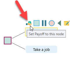
    When you click the payoff button for the first time, the setup window appears if you have not already configured criteria.

    First-time payoff intent window letting the user choose between Regular single or multiple criteria based analysis and Cost-Effectiveness Analysis in Healthcare.
    First-time payoff intent window letting the user choose between Regular single or multiple criteria based analysis and Cost-Effectiveness Analysis in Healthcare.

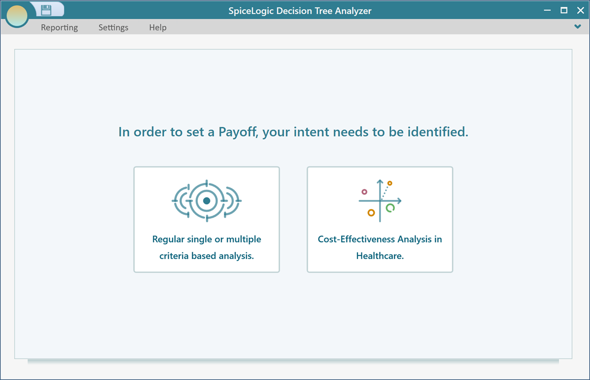
    The software needs to know what type of payoff your model uses. It can be numeric, subjective, Boolean, or cost-effectiveness based. This setup window asks whether you want a regular single- or multiple-criteria analysis, or a healthcare-focused cost-effectiveness analysis.

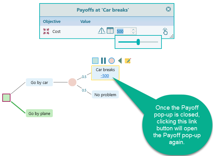
    After criteria are configured, the payoff popup appears on the node. You can enter payoffs for multiple objectives at the same time.

    Inline payoff editor opened on an event node so the user can enter the value for this branch.
    Inline payoff editor opened on an event node so the user can enter the value for this branch.

    Parallel Node

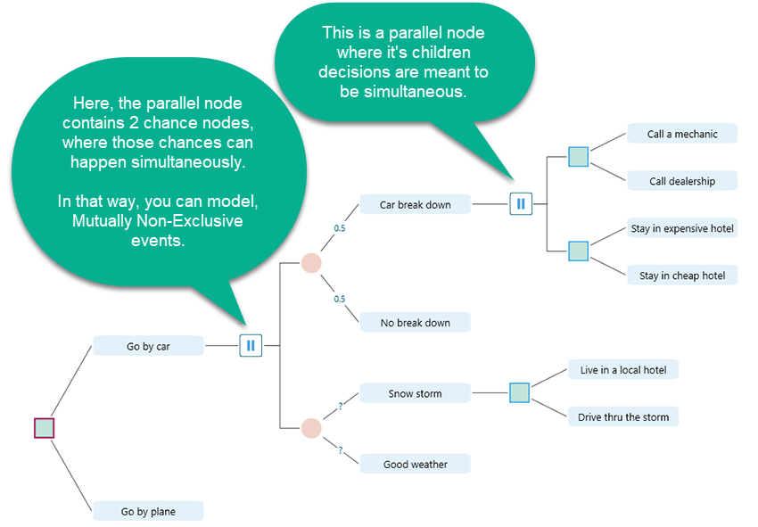
    A parallel node is a SpiceLogic extension, not a standard decision-tree concept. Use it when a node has children that should be treated as simultaneous decision trees. For example, you may need to model two decision problems at the same time, or two chance events that are not mutually exclusive.

    Diagram explaining the SpiceLogic-specific Parallel node (drawn with two vertical bars), whose child sub-trees represent simultaneous, mutually non-exclusive branches rather than alternatives.
    Diagram explaining the SpiceLogic-specific Parallel node (drawn with two vertical bars), whose child sub-trees represent simultaneous, mutually non-exclusive branches rather than alternatives.

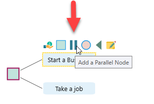
    A parallel node can be added under an action node or an event node. The fly-over menu shows the parallel-node button when it is valid for the selected node.

    Flyover menu on an Action or Event node with the button highlighted that adds a Parallel node as a child.
    Flyover menu on an Action or Event node with the button highlighted that adds a Parallel node as a child.

    Terminal Node

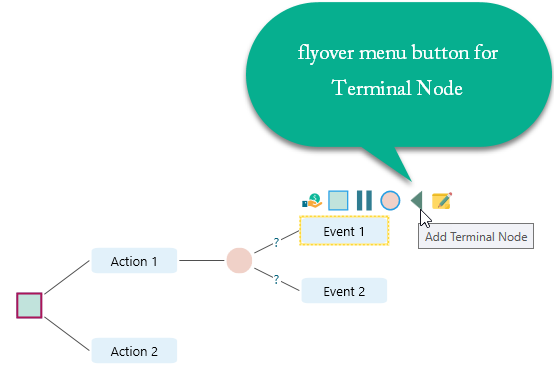
    An action node or event node can end with a terminal node. When you select an action node or event node, the fly-over menu shows the terminal-node button.

    A decision node or chance node cannot be directly terminated by a terminal node because those nodes can only contain actions or events as children. So the terminal-node option does not appear when a decision node or chance node is selected.

    Flyover menu on an Action or Event node showing the Terminal Node button used to close that branch.
    Flyover menu on an Action or Event node showing the Terminal Node button used to close that branch.

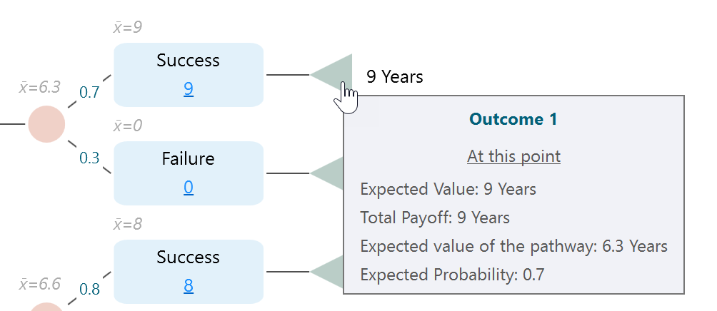
    Using a terminal node is optional. It does not change the calculation logic. Its main benefit is that it displays the total payoff for that terminal path.

    Terminal node displaying the total payoff accumulated along the branch it closes.
    Terminal node displaying the total payoff accumulated along the branch it closes.

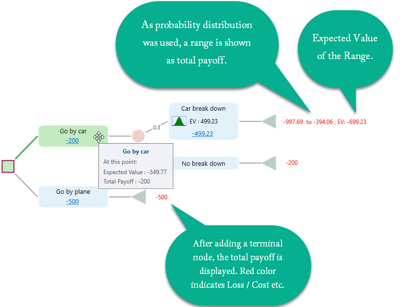
    The terminal node also shows useful metrics in a tooltip.

    Tooltip on a Terminal node listing the full set of branch metrics including expected value, total payoff, and path probability.
    Tooltip on a Terminal node listing the full set of branch metrics including expected value, total payoff, and path probability.

    Last updated on Jun 16, 2026